Texas Instruments pinctrl in the Devicetree Manager
Texas Instruments chips write pinctrl in three ways. This page covers each one:
- MSPM0 G and L, MSPM33C: pin nodes, like STM32
- CC13xx, CC26xx and CC23x0: pin nodes that each board names itself
- CC32xx: pin groups, like NXP
It ends with the MSPM0 clock tree.
MSPM0 and MSPM33C
Every pin function is a pin node: uart0_tx_pa10 is UART0 TX on PA10. TI's pin file for the chip defines these nodes, with the settings each signal needs:
uart0_tx_pa10: uart0_tx_pa10 {
    pinmux = <MSP_PINMUX(21, MSPM0_PIN_FUNCTION_2)>;
};

uart0_rx_pa11: uart0_rx_pa11 {
    pinmux = <MSP_PINMUX(22, MSPM0_PIN_FUNCTION_2)>;
    input-enable;
};
The manager reads every function of your exact part from the TI HAL your build already uses. So it offers the functions TI's pin file has no node for, and it works on a board that defines its own pin nodes.
The screenshot uses the LP-MSPM0G3507 LaunchPad (lp_mspm0g3507).
Route a pin
Click a pad, then the signal in the Functions card (see Pin configuration). The manager adds the pin node to the peripheral's pinctrl-0:
&uart3 {
    pinctrl-0 = <&uart3_tx_pa26 &uart3_rx_pa25>;
    pinctrl-names = "default";
};
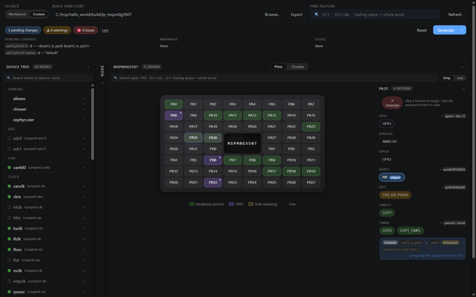
Timer pins (CCP0, CCP1_CMPL, ...) go to the timer's PWM node, for example pwma0 for tima0.
The ANALOG and GPIO functions of a pad belong to no peripheral. When you pick one, the manager asks which node gets the pin, for example an ADC.
A function with no pin node
When no pin node exists for the function you pick, the manager creates it, with TI's naming and Zephyr's macro. On the BeagleConnect Zepto (MSPM0L1117), routing SPI0 writes:
#include <dt-bindings/pinctrl/mspm0-pinctrl.h>

&spi0 {
    pinctrl-0 = <&spi0_sclk_pa6 &spi0_pico_pa5 &spi0_poci_pa4>;
    pinctrl-names = "default";
};

&pinctrl {
    spi0_sclk_pa6: spi0_sclk_pa6 {
        pinmux = <MSP_PINMUX(11, MSPM0_PIN_FUNCTION_3)>;
    };
};

&pinctrl {
    spi0_pico_pa5: spi0_pico_pa5 {
        pinmux = <MSP_PINMUX(10, MSPM0_PIN_FUNCTION_3)>;
    };
};

&pinctrl {
    spi0_poci_pa4: spi0_poci_pa4 {
        pinmux = <MSP_PINMUX(9, MSPM0_PIN_FUNCTION_3)>;
        input-enable;
    };
};
A node it creates gets the settings TI's pin files give that signal:
| Peripheral | Settings |
|---|---|
| UART | RX and CTS: input-enable |
| I2C | SDA and SCL: input-enable, drive-open-drain and bias-disable |
| SPI | POCI: input-enable |
| CAN | RX: input-enable |
A node TI's pin file defines keeps its own settings.
The build does not say which package your chip has. The chip view shows every pin of the part's series: check your package's pinout before you route a pin.
On Zephyr 4.4 and 4.5, the LP-MSPM0G3519 board uses the pin file of the MSPM0G350x, so some of its pin names are wrong for that chip. The header lists them, for example "canfd0_cantx_pa12 sets PA12 to TIMA0_CCP3 on MSPM0G3519, not CANFD0_CANTX." The chip view shows what each pin really does.
CC13xx, CC26xx and CC23x0
On these chips, each board names its own pin nodes. A pin node holds two numbers: the DIO, then the function.
&pinctrl {
    uart0_tx_default: uart0_tx_default {
        pinmux = <13 IOC_PORT_MCU_UART0_TX>;
        bias-disable;
    };
};

&uart0 {
    pinctrl-0 = <&uart0_rx_default &uart0_tx_default>;
    pinctrl-names = "default";
};
The manager finds the node of a function by its two numbers, whatever the board called it. When you pick a function that has no node, it creates one. Adding CTS and RTS to UART0 on the CC1352R1 LaunchPad writes:
#include <dt-bindings/pinctrl/cc13xx_cc26xx-pinctrl.h>

&uart0 {
    pinctrl-0 = <&uart0_rx_default &uart0_tx_default &uart0_cts_dio19 &uart0_rts_dio18>;
};

&pinctrl {
    uart0_cts_dio19: uart0_cts_dio19 {
        pinmux = <19 IOC_PORT_MCU_UART0_CTS>;
        bias-disable;
        input-enable;
    };
};

&pinctrl {
    uart0_rts_dio18: uart0_rts_dio18 {
        pinmux = <18 IOC_PORT_MCU_UART0_RTS>;
        bias-disable;
    };
};
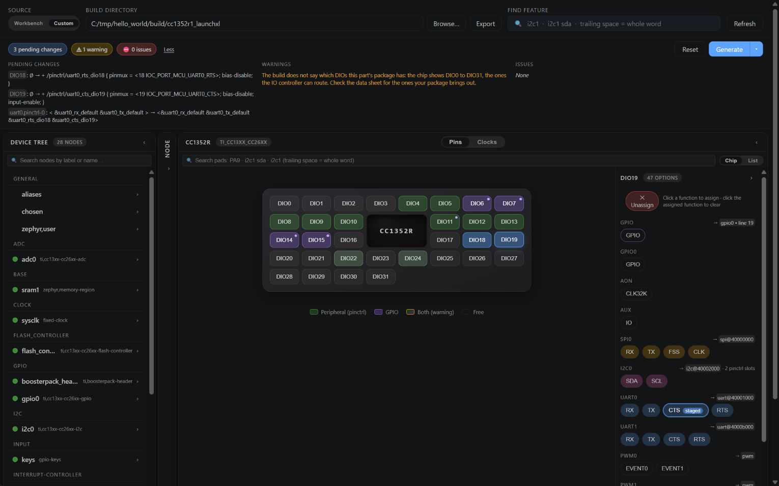
A node the manager creates gets bias-disable, plus input-enable on an input. I2C lines get bias-pull-up, drive-open-drain and input-enable.
What differs between the two families:
- CC13xx and CC26xx: any function can go to any DIO. A pin node must set its pull (
bias-disable,bias-pull-uporbias-pull-down): the header warns about a node that sets none. - CC23x0: each DIO has its own list of functions. A timer pin goes to the PWM node of its timer channel.
A board can give a pin another function for its sleep state (pinctrl-1). The pad's tooltip shows both, for example "DIO4 → i2c0 (SCL), gpio0 (GPIO) in sleep".
On CC13xx and CC26xx, the build does not say which DIOs your package has. The chip view shows DIO0 to DIO31: check your package's pinout.
CC32xx
CC32xx uses pin groups: the peripheral points to one node, whose group lists the pins. A pin is named after its function and its package pin: UART1_TX_P58 is UART1 TX on pin 58. Routing UART1 on the CC3220SF LaunchPad writes:
#include <dt-bindings/pinctrl/ti-cc32xx-pinctrl.h>

&uart1 {
    pinctrl-0 = <&uart1_default>;
    pinctrl-names = "default";
};

&pinctrl {
    uart1_default: uart1_default {
        group1 {
            pinmux = <UART1_TX_P58>, <UART1_RX_P59>;
            drive-strength = <6>;
        };
    };
};
The pads of the chip view are the package pins (P1 to P64).
MSPM0 clocks
The Clocks view covers MSPM0 G and L from Zephyr 4.4. MSPM33C needs the Zephyr release after 4.5.
It shows SYSOSC, the crystals, the PLL with its outputs, then MCLK, ULPCLK and the other clocks, with the peripherals on each one.
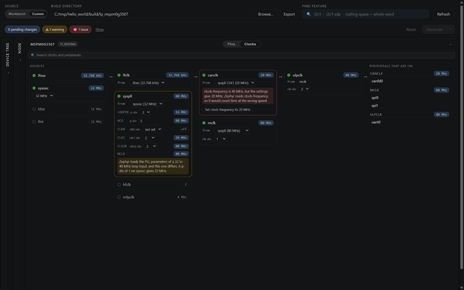
The view offers only what each series has: for example ULPCLK has no divider on the L series, and the MSPM0L110x has no crystal.
It flags as errors the settings Zephyr's clock driver refuses to build or to start, for example:
- SYSOSC at another frequency than 4 MHz or 32 MHz.
- The PLL on while SYSOSC runs at 4 MHz.
- A clock that is on while its source is off.
It also compares each clock-frequency with what the settings give. In the screenshot, the LaunchPad of Zephyr 4.5 states 40 MHz for its CAN clock, and its PLL settings give 20 MHz: the box says so and offers Set clock-frequency to 20 MHz.
CC13xx, CC26xx, CC23x0 and CC32xx have one fixed system clock in the devicetree. The view shows it with the peripherals on it, and there is nothing to change.