GPIOs in the Devicetree Manager
A Zephyr pin is used in one of two ways. A peripheral takes it through pinctrl (pinctrl-0), or a node uses it as a GPIO through a property ending in -gpios, like this LED:
led_3 {
    gpios = <&gpiod 13 GPIO_ACTIVE_HIGH>;
};
The Devicetree Manager shows both on the chip. It warns you when a pin has two owners, and lets you move a GPIO or change its settings in the node editor.
What counts as a GPIO
The manager reads the build's resolved devicetree, so it sees the same GPIOs Zephyr does:
- Every property whose name ends in
-gpios: thegpiosof an LED or a button,cs-gpiosof a SPI bus,reset-gpios,enable-gpiosorint-gpiosof a device, and your own<name>-gpiosinzephyr,user. - A property ending in
-gpio(singular), only when its binding declares it as a GPIO (specifier-space: gpio). Zephyr's own bindings always use-gpios. - Pins a GPIO hog node sets at boot.
- Pins reached through a board connector, like
<&arduino_header 13 0>: they count on the chip pin the connector leads to.
In zephyr,user, always end GPIO property names with -gpios. A singular -gpio name there fails the devicetree build.
A GPIO your code drives without a devicetree property (a port and pin number written in C) is not visible to the manager. Describe your pins in the devicetree and read them with GPIO_DT_SPEC_GET.
How a GPIO finds its pin
A GPIO names a port and a line: <&gpiod 13 ...> is line 13 of port gpiod. The manager knows how each vendor names its ports:
| Vendor | Ports | Example |
|---|---|---|
| STM32, Silicon Labs | gpioa, gpiob, ... | gpiod line 13 is PD13 |
| NXP MCX | gpio0, gpio1, ... (gpioa, ... on MCXW) | gpio0 line 4 is port 0, pin 4 |
| ESP32 | gpio0, gpio1 | gpio1 line 2 is GPIO34 |
| Renesas RA | ioport0, ioport1, ... | ioport1 line 6 is P106 |
| Infineon | gpio_prt0, ... (gpio0, ... on XMC4) | gpio_prt5 line 0 is P5.0 |
A GPIO of an I/O expander (a separate chip on I2C or SPI) is not a pin of your MCU: it shows in the node editor, not on the chip.
See GPIOs on the chip
The chip uses these colours (a legend sits under it):
- Green: a peripheral uses the pin.
- Violet, with a small dot: a node uses the pin as a GPIO.
- Green and violet, with an amber "!": the pin has two owners (see below).
- Faded violet: only disabled nodes use the pin.
- Dashed outline: a staged change. Amber dashed outline: in the overlay file, not built yet.
Hover a pin to see who uses it, for example PD13 → tim4 (CH2) · GPIO: orange_led_3 (gpios).
Click a pin. The Functions card starts with a "gpio" section: the port and line (gpiod • line 13) and a "GPIO" chip, like the other functions. Its badge says "in use", "staged" or "disabled" when a node uses the pin as a GPIO. Under the functions, a GPIO row names each node and property, for example GPIO orange_led_3 → gpios. Click the node name to open the node.
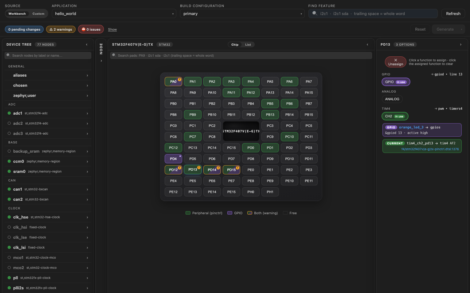
The search boxes find GPIOs too: type gpio, led or reset-gpios.
Pins with two owners
When a pin is a GPIO of one node and also routed to a peripheral (or a GPIO of two nodes), both drivers set it up, and the one that starts last wins. The header shows a warning, for example:
PD12, PD13, PD14, PD15: used as GPIO by green_led_4, orange_led_3, red_led_5, blue_led_6 and routed to tim4. Whichever driver starts last owns the pin.
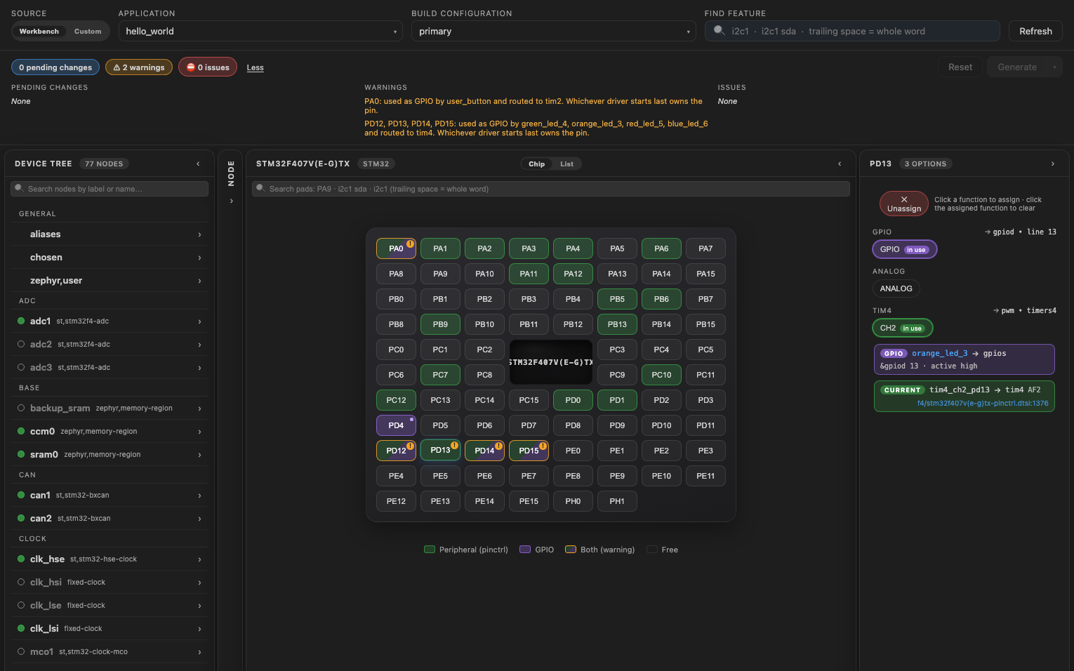
To keep one owner:
- Click the pin.
- In the Functions card, either click "Unassign" to remove the peripheral, or click the node name in its GPIO row and move the GPIO to another pin (see Edit a GPIO).
Some boards ship with such overlaps. On the STM32F4 Discovery, the four user LEDs are both GPIO LEDs and PWM LEDs: that is fine as long as your application uses only one of the two.
A node may use its own pin as a GPIO without a warning. For example, an I2C controller's scl-gpios, used to free a stuck bus, is the same pin as its SCL.
Edit a GPIO
Each GPIO property opens as a table in the node editor, one row per pin:
- Open the node: click its name in a GPIO row of the Functions card, or select it in the Device Tree list.
- Pin: pick the new pin by name. Free pins come first, and pins in use say who holds them. A pin on another port changes the port too.
- Active: "High" if the device is on when the pin is high, "Low" otherwise.
- Pull: "None", "Up" or "Down".
- Drive: "Push-pull" or "Open drain".
- ✕ removes the pin. + Add pin adds one more, for a property that takes several pins (one per chip select in
cs-gpios, for example).
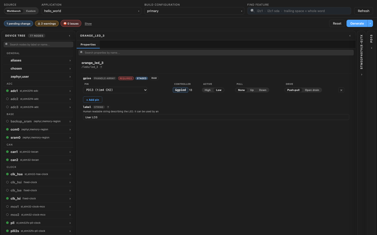
Click "raw" to edit the value as text instead.
Then generate the overlay (see Generate the overlay). The new value uses Zephyr's flag names, and the overlay includes the header that defines them:
&orange_led_3 {
    gpios = <&gpiod 7 (GPIO_ACTIVE_LOW | GPIO_PULL_UP)>;
};
Rebuild the application to apply it.
Input or output is not part of the devicetree: your code chooses it when it configures the pin. The table edits what the devicetree holds.
Other checks
- Disabled port: a GPIO on a port whose node is disabled does not work. The header warns you; set the port node's
statustookay. - Line out of range: an error when the line is past the number of lines of the port.
Give a pin to a GPIO property
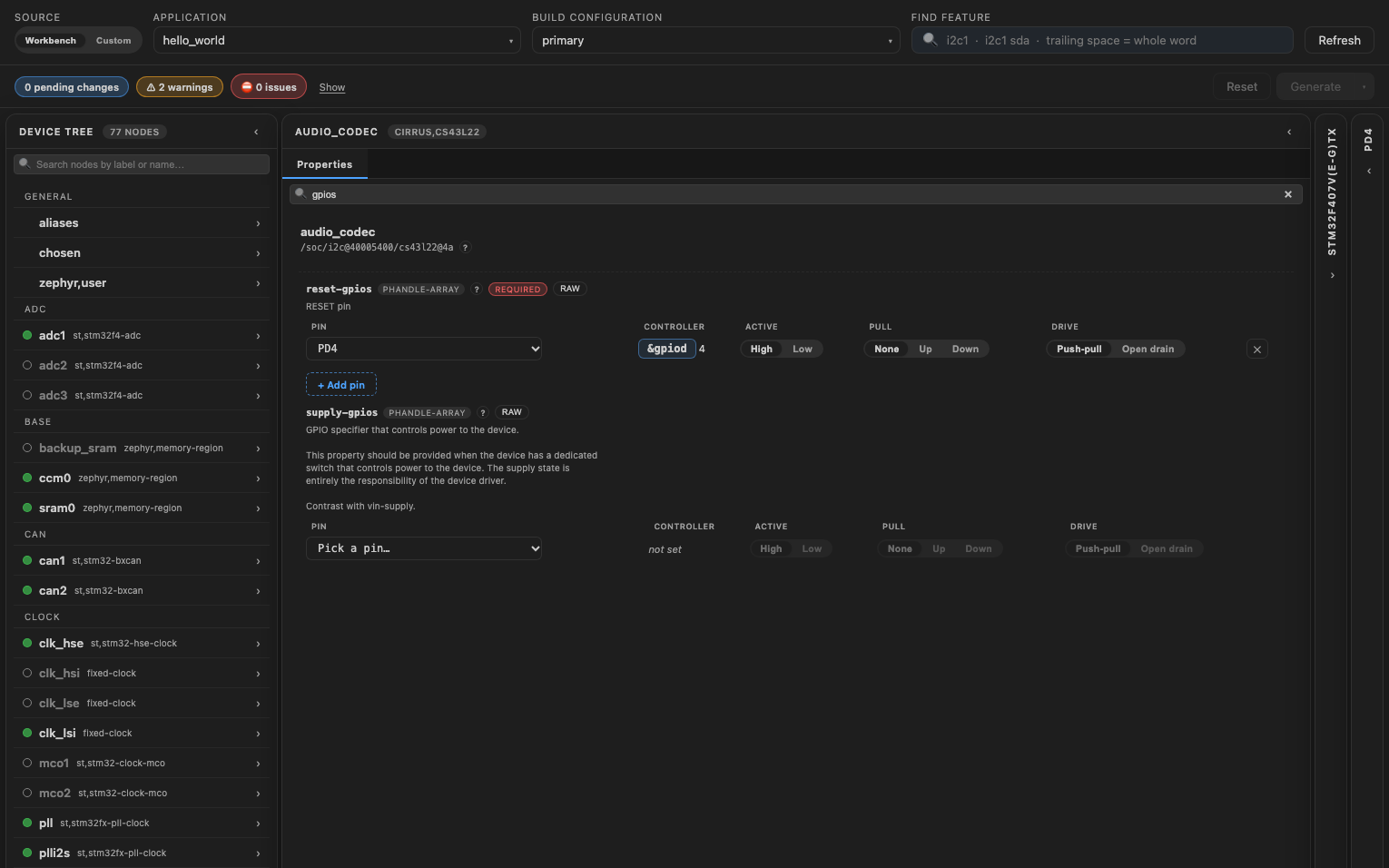
A device often has a GPIO property that is not set yet, for example supply-gpios on an audio codec, cs-gpios on a SPI bus or int-gpios on a sensor. Give it a pin from the node or from the pin.
From the node:
- Open the node. The property shows a row with "Pick a pin…".
- Read the description under the property name: bindings usually say there whether the line is active high or low.
- Pick the pin. Free pins come first.
- Set Active, Pull and Drive if needed. A new pin starts as active high, no pull, push-pull.
From the pin:
- Click a free pin on the chip.
- In the Functions card, click GPIO. A list of the GPIO properties that are not set opens. The node open in the node editor comes first, disabled nodes come last.
- Type in the filter box to narrow the list, then click the property.
- Set Active, Pull and Drive, then click Assign.
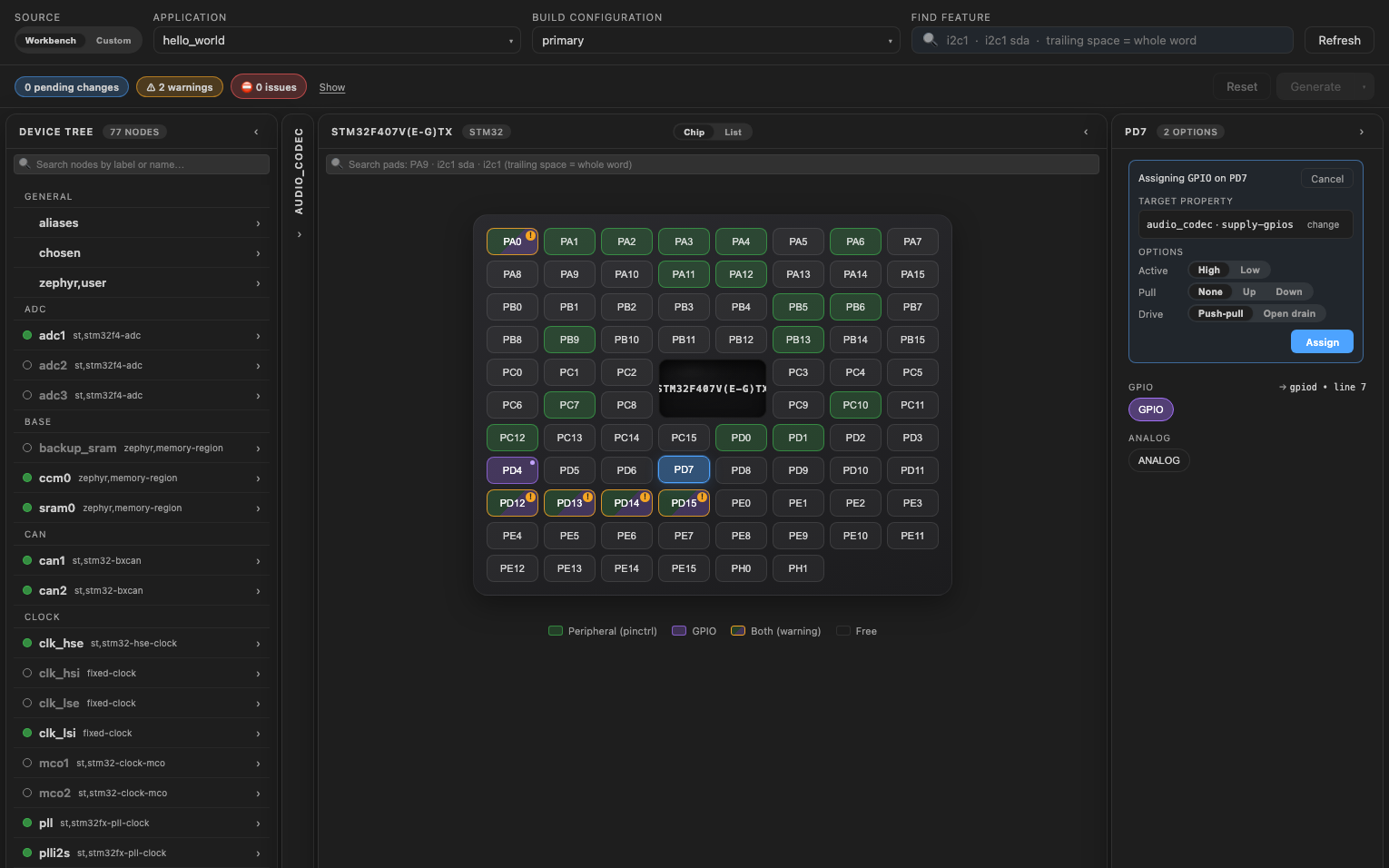
The pin shows as staged on the chip. To take it back, click GPIO again.
On Renesas RA, a board turns on only the ports it uses. A pin on a port that is off also turns that port on, and taking the pin back turns the port off again.
Add a new GPIO
- A new LED or button: open the LED (or button) node, for example
leds, go to its Children tab and click "+ Add child". The new child'sgpiosshows the "Pick a pin…" row, and the pin can also be given from the chip as above. - A GPIO for your application: on
zephyr,user, click "+ Add" and name the property<name>-gpios, with a value such as< &gpioe 7 GPIO_ACTIVE_HIGH >. It shows on the chip right away.