SPI in the Devicetree Manager
A Zephyr SPI bus is a controller node with its clock and data pins (SCK, MOSI and MISO), a chip select GPIO per device in cs-gpios, and one child node per device on the bus. The Devicetree Manager sets up the controller and its chip selects, checks its pins and writes the result to your devicetree overlay.
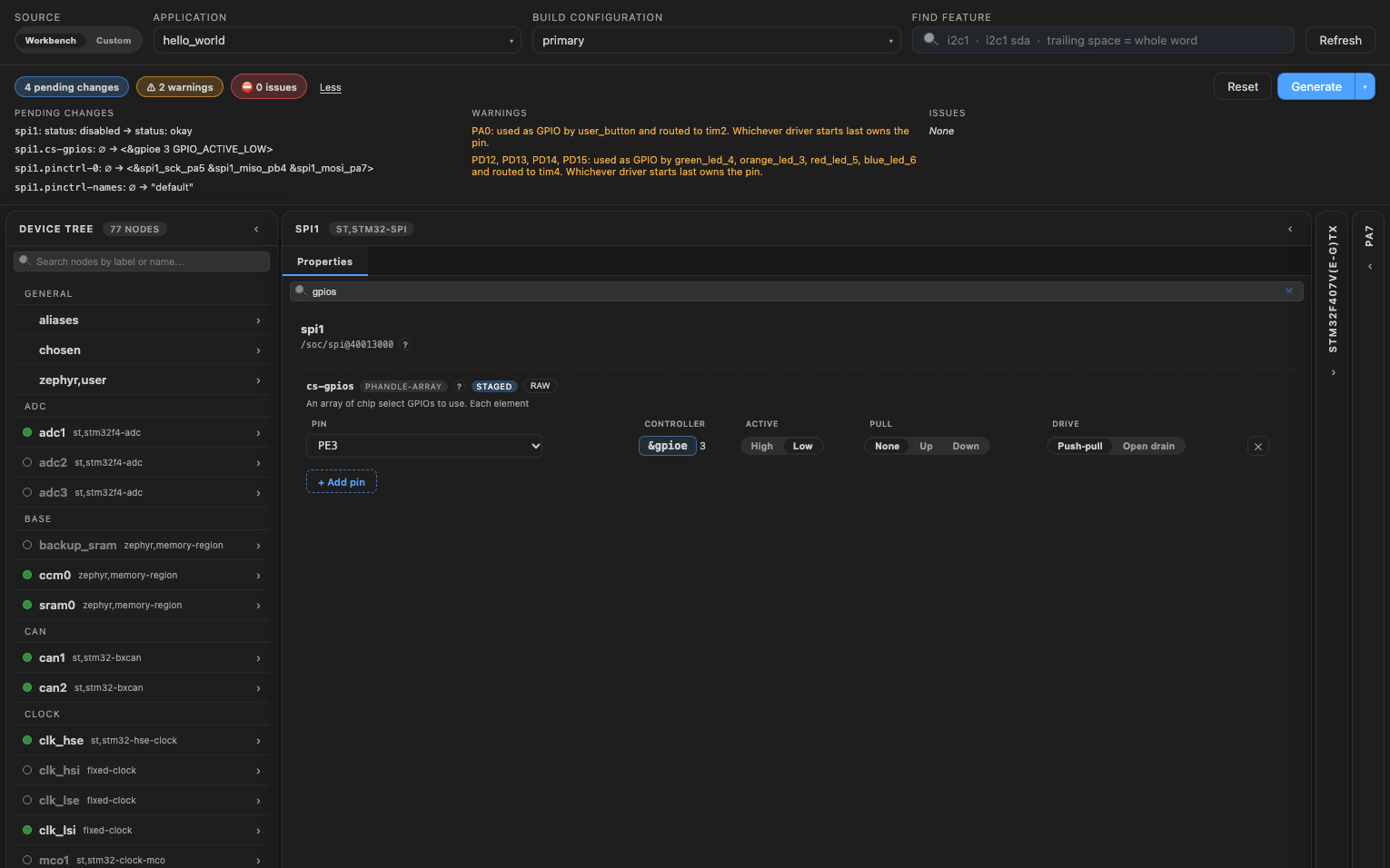
The screenshot uses the STM32F4 Discovery board (stm32f4_disco). The steps are the same on the other supported vendors.
Set up the controller
- Select the controller in the Device Tree list, for example
spi1. - If its
statusisdisabled, set it tookay. - Give it SCK, MOSI and MISO. Type it in the "Find feature" box, click a pad that lights up, then click the signal in the Functions card. The header flags MOSI or MISO without SCK.
Chip selects
Give each device a chip select in cs-gpios, one row per device:
- Pick the pin in the Pin column. Free pins come first.
- Set Active to "Low": chip selects are usually active low.
- Click + Add pin for the next device.
The first row is the chip select of the device with reg = <0>, the second of the device with reg = <1>, and so on. The table works like any GPIO property (see Edit a GPIO).
Devices on the bus
Each device on the bus is a child node of the controller, edited in its Children tab. Its reg is its row in cs-gpios, and spi-max-frequency is the fastest clock it accepts.
The Children tab lists the devices the board or your overlay already puts on the bus. To add a device, write its node in the overlay, outside the generated block, then rebuild:
&spi1 {
    bme280@0 {
        compatible = "bosch,bme280";
        reg = <0>;
        spi-max-frequency = <1000000>;
    };
};
Write the overlay
Click "Generate" to write your changes to the overlay, then rebuild the application. See Generate the overlay.