Devicetree Manager
The Devicetree Manager is a visual editor for the pin muxing and the devicetree of a Zephyr application. Think of it as a CubeMX-style pin and peripheral configurator, but vendor-agnostic: instead of being tied to one silicon vendor, it works from Zephyr's resolved devicetree, which is the same model for every board and every vendor.
You pick an application and one of its build configurations, explore the resolved devicetree of that build, configure pins and peripherals, then generate the result as a board overlay file (boards/<board>.overlay) in the application folder.
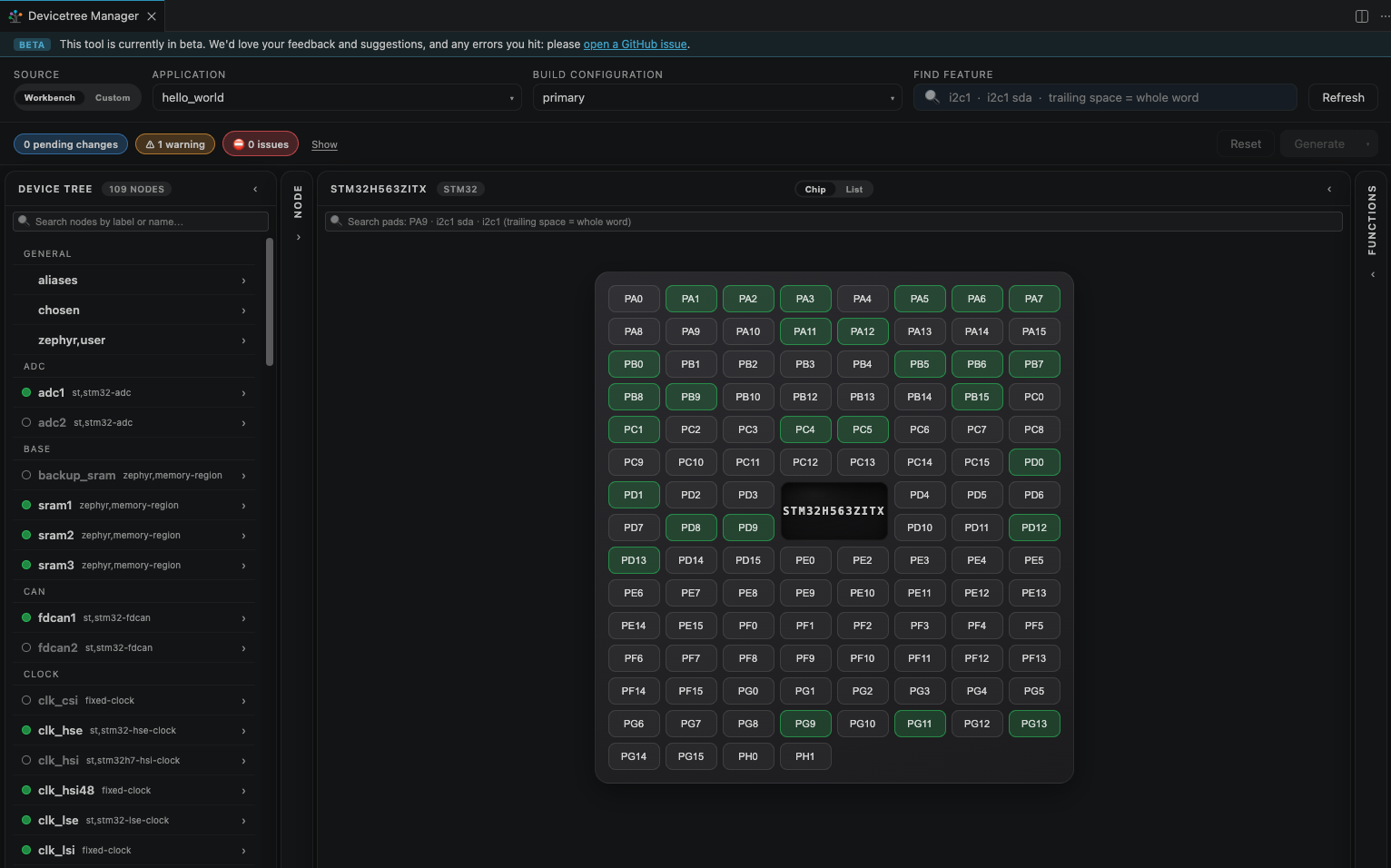
Browsing the devicetree, editing node properties and generating the overlay work with any board, whatever its vendor.
The interactive chip pinout (the pin configurator) needs a vendor backend to map signals to pads. It currently supports STM32, NXP (including i.MX RT), ESP32 and Silicon Labs families. On a board from another vendor, the chip view shows an unsupported state while the rest of the editor keeps working.
More families are on the way. To request one, or to contribute a backend, open an issue or a pull request on the companion extension's GitHub repository.
Companion extension
The editor ships in a separate companion extension, Devicetree Manager for Zephyr (Ac6.devicetree-manager-for-zephyr). It is part of the Workbench extension pack, so it is installed automatically alongside Workbench for Zephyr.
Workbench for Zephyr stays fully usable without the companion extension. If it is missing (for example after uninstalling it), opening the Devicetree Manager shows an install hint instead; install "Devicetree Manager for Zephyr" from the marketplace to enable the feature.
Open the Devicetree Manager
Use one of:
- The "Devicetree Manager" item in the "Workbench for Zephyr" shortcuts view
- The command palette: "Zephyr Workbench: Devicetree Manager"
- The "DT Manager" status bar item
The "DT Manager" item sits next to "Build" and "Debug" in the status bar. It appears automatically when the active editor is a devicetree source file (.dts, .dtsi or .overlay) that belongs to a Zephyr application, and opens the manager preselected to that application and its first build configuration.
When opened from the shortcuts view or the command palette, pick the target in the editor header:
- Application: choose the Zephyr application.
- Build Configuration: choose one of its build configurations.
The Devicetree Manager reads the resolved devicetree from the build directory, so build the application (at least once) before using it. If your build lives outside a Workbench application, switch the "Source" toggle to "Custom" and point the "Build directory" field at the folder that contains build_info.yml.
Configure a peripheral, guided by the tool
The Devicetree Manager guides you to a valid configuration. Enable a peripheral and it flags whatever is still missing until every required field and signal is set. Follow the issues in the header and they disappear one by one. Here is the flow for an I2C controller (i2c2).
- Start from the default. Select the peripheral in the device tree. On a fresh board it is usually
disabled.
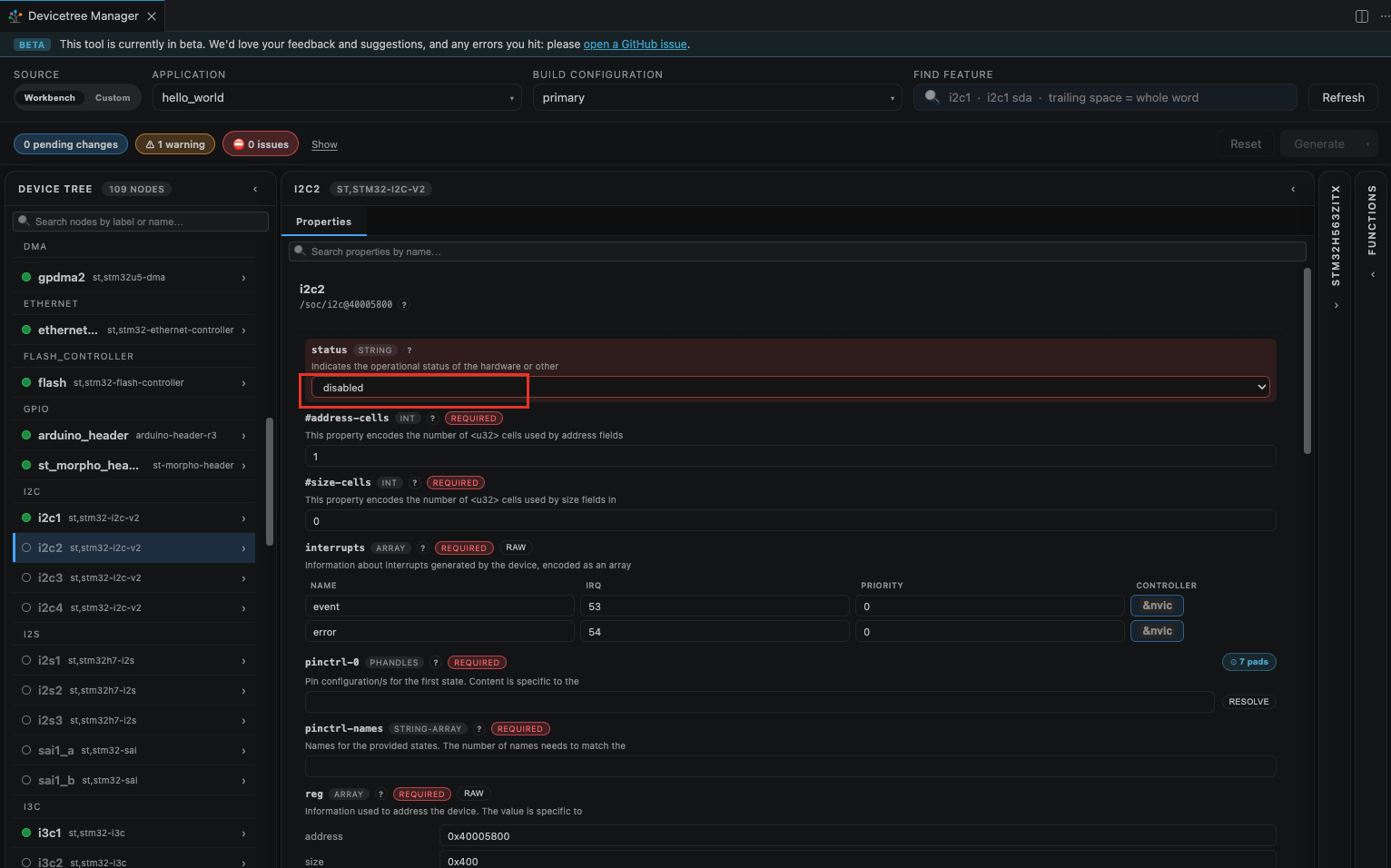
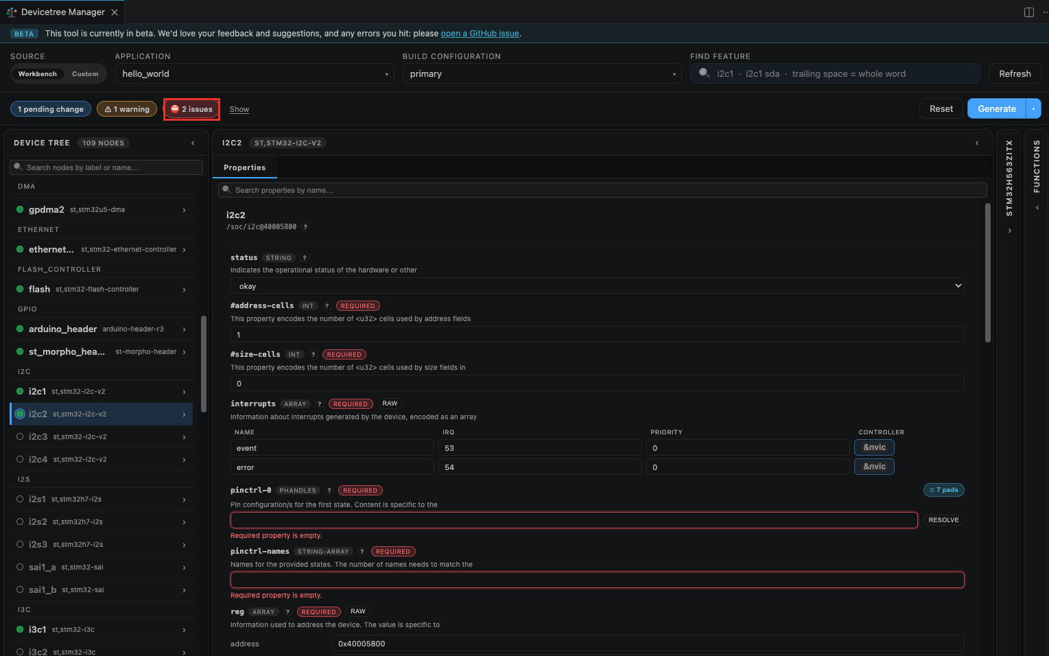
- Enable it. Set
statustookayin the Properties pane. The peripheral now needs its pins, so the header reports issues (here "2 issues": the requiredpinctrl-0andpinctrl-namesare still empty).
- Open the pin picker. With the peripheral selected (or searched in the "Find feature" box), the pads that can carry its signals light up on the chip. Click one of the highlighted pads.
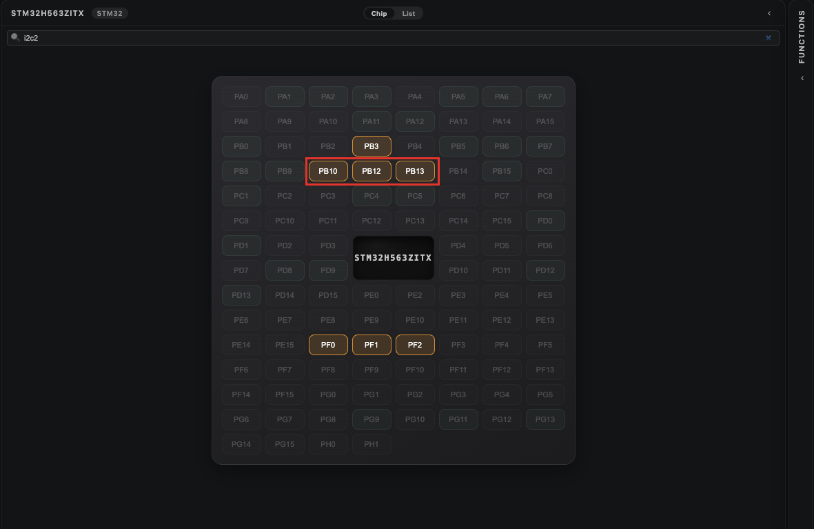
- Assign the clock (SCL). Pick the I2C clock function on the pad you clicked. One signal is set, but I2C also needs data, so one issue remains.
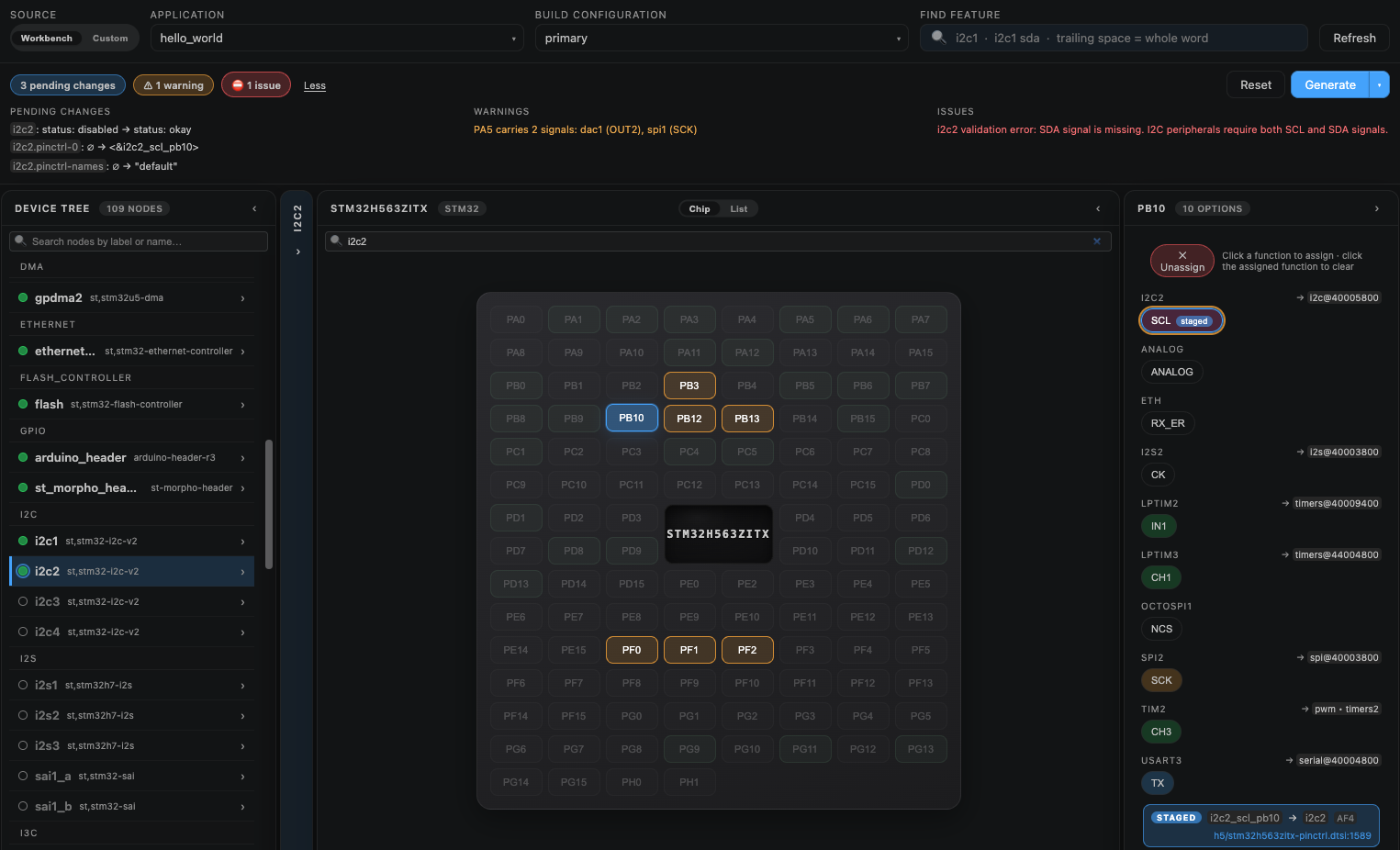
- Assign the data (SDA). Add the data signal the same way. With both SCL and SDA set, the header reads "0 issues" and the peripheral is ready.
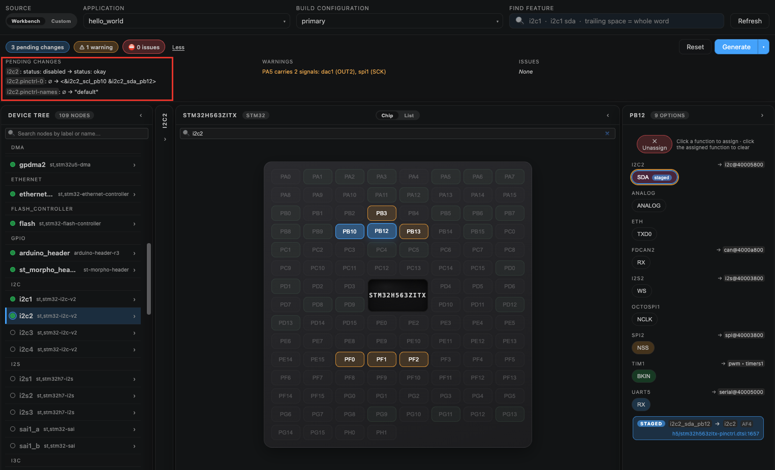
Other properties (interrupts, registers, and so on) are editable in the same Properties pane.
Generate the overlay
Your pin and property changes are staged in the editor, not written yet. Click "Show" in the header to review the pending-changes list and any remaining warnings or issues.
- Click "Generate" to write the staged changes to
boards/<board>.overlayin the application folder. - Rebuild the application to apply the new overlay.
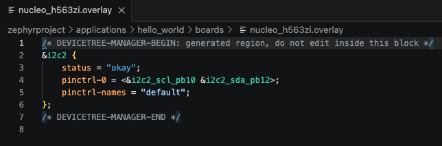
The generated block is delimited by DEVICETREE-MANAGER-BEGIN / DEVICETREE-MANAGER-END markers. Keep your manual edits outside this region: the manager rewrites it on the next Generate.
The arrow next to "Generate" opens two options:
- Mode: "Modify" (default) merges into the existing overlay, updating nodes that are already there and adding the rest. "Append" leaves the existing content untouched and adds the generated block at the end.
- Target: "Overlay file" (default) writes
boards/<board>.overlay; "Untitled" opens the result in a new unsaved editor so you can review it first.
After generating, the editor shows a rebuild banner listing the overlay changes that are not in the current build yet. Rebuild the application to clear it.
Related tools
- DTS LSP Integration: language features (hover, go-to definition, diagnostics, formatting) when editing
.dtsand.overlayfiles by hand. The Devicetree Manager is the visual counterpart; both work on the same files. - DT Doctor: runs devicetree static analysis on a build and reports diagnostics in the terminal. Use it to check a configuration, and the Devicetree Manager to fix it.