STM32 pinctrl in the Devicetree Manager
On STM32, every pin function has a ready-made pin node in ST's pin file for your chip: usart3_tx_pd8 is USART3 TX on PD8, alternate function 7. The node also holds the pin settings ST chose for that signal:
usart3_tx_pd8: usart3_tx_pd8 {
    pinmux = <STM32_PINMUX('D', 8, AF7)>;
    bias-pull-up;
};
The screenshot uses the STM32F4 Discovery board (stm32f4_disco).
STM32 F1 is not supported: its pins use remaps, which the chip view doesn't read yet. See Supported devices.
Route a pin
Click a pad, then the signal in the Functions card (see Pin configuration). The manager adds the pin node to the peripheral's pinctrl-0:
&usart3 {
    status = "okay";
    pinctrl-0 = <&usart3_tx_pd8 &usart3_rx_pd9>;
    pinctrl-names = "default";
};
Timer pins (CH1, CH2N, ...) go to the timer's pwm node, which is where Zephyr expects them (see PWM).
Change pin settings
ST's pin files already set what most signals need: a pull-up on a UART TX, open drain and pull-up on I2C, a high slew rate on SPI clocks. To change a pin:
- Open the peripheral and click the pin in its
pinctrl-0, for example&usart2_tx_pa2. - Its pin node opens. Check or uncheck
bias-pull-up,bias-pull-down,bias-disable,drive-push-pull,drive-open-drain,output-loworoutput-high, and pick aslew-rate.
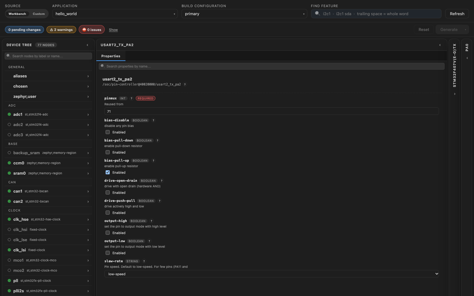
The overlay then overrides that pin node:
&usart2_tx_pa2 {
    /delete-property/ bias-pull-up;
    bias-pull-down;
};
ST's pin files keep only the pin nodes a build uses. A pin you just routed shows as "(not found)" in pinctrl-0 until you generate the overlay and rebuild. After the rebuild, you can open it and change its settings.