PWM outputs in the Devicetree Manager
A Zephyr PWM output is a pin driven by a timer channel. A node uses it through its pwms property: the PWM controller, the channel, the period and the flags. Here is an LED of the STM32F4 Discovery:
red_pwm_led: red_pwm_led {
    pwms = <&pwm4 3 PWM_USEC(100) PWM_POLARITY_NORMAL>;
};
The Devicetree Manager lets you pick the pin by name and writes the rest to your devicetree overlay. The screenshots use the STM32F4 Discovery board (stm32f4_disco). The steps are the same on the other supported vendors.
The pwms table
Each pwms property opens as a table, one row per output:
- Pin: pick the pin by name. Each pin shows the timer channel it drives, for example
PD14 · tim4 CH3. Free pins come first. - Period: a number and a unit (ms, µs, ns, s, Hz or kHz). The line under it shows the period and the frequency, for example "100 µs (10 kHz)". Changing the unit keeps the period.
- Polarity: "Normal" or "Inverted".
- ✕ removes the output. + Add pin adds one.
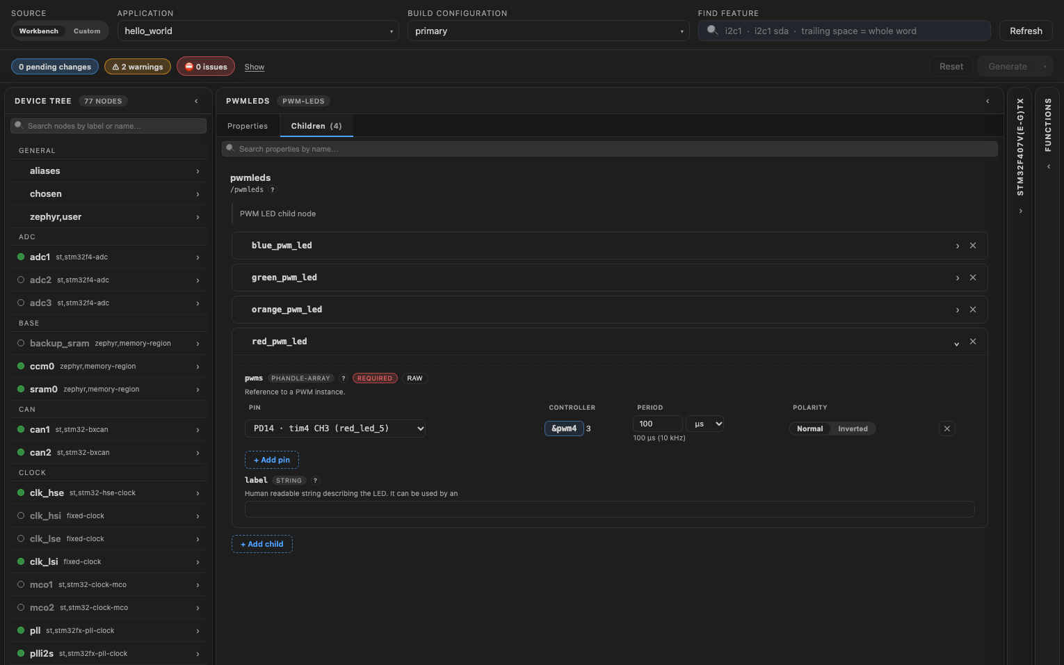
You never type the channel number: the manager writes it from the pin, with each vendor's numbering. Picking a pin also stages what the output needs:
- The pin, routed to the timer.
- The timer, turned on.
- A label for the timer's PWM node when the board has none (for example
pwm3), so thepwmsentry can point to it. - On ESP32 LEDC, the channel node the driver needs.
Picking the previous pin again takes all of it back.
The Outputs tab
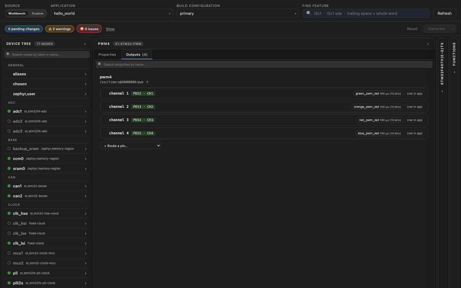
Open the PWM controller (click its chip in the table, for example &pwm4), then its Outputs tab. Each channel shows its pin, the nodes that use it with their period, and Use in app. "+ Route a pin…" routes one more of its pins.
Read the output in your application
Use in app adds the output to the pwms property of zephyr,user. Your code reads it by its position there, as the button's tooltip shows:
static const struct pwm_dt_spec pwm_output =
    PWM_DT_SPEC_GET_BY_IDX(DT_PATH(zephyr_user), 0);
What the manager checks
The header flags:
- An output on a disabled controller.
- Channel 0 on an STM32 timer: its channels start at 1.
- A channel with no pin routed. The message names the pins that can carry it.
- Two periods on one timer. Most timers share one period across their channels, and the last one set wins.
- An STM32 complementary pin (
CH1N) without its flag, or the flag without the pin. - An ESP32 LEDC channel without its channel node.
pwm-namesinzephyr,userthat do not matchpwmsone for one.
Write the overlay
Click "Generate" to write your changes to the overlay, then rebuild the application. The overlay includes the header that defines PWM_USEC and the other names it uses. See Generate the overlay.