Infineon pinctrl in the Devicetree Manager
Infineon chips use pin nodes, like STM32: each pin function is a node, and the peripheral's pinctrl-0 lists them. This page covers two families:
PSoC and XMC7000
A pin node is named after the pin and the function: p5_1_scb5_uart_tx is SCB5 UART TX on P5.1.
&scb5 {
    pinctrl-0 = <&p5_1_scb5_uart_tx &p5_0_scb5_uart_rx>;
};
Zephyr defines only part of the pin nodes of each chip. The manager offers every function of the chip, from Infineon's own tables, and creates a missing node when you pick it, with Zephyr's naming (p5_0_scb5_spi_m_mosi) and macro (DT_CAT1_PINMUX).
The screenshot uses the CY8CPROTO-062-4343W board.
Pin settings
An Infineon pin with no drive, bias or input setting stays analog and does nothing, and Zephyr's pin nodes set none. So the manager writes Infineon's defaults on every pin it routes:
| Mode | Settings |
|---|---|
| UART | TX and RTS: drive-push-pull. RX and CTS: input-enable |
| I2C | drive-open-drain and input-enable |
| SPI | SCK, MOSI and CS: drive-push-pull. MISO: input-enable |
The header warns about a pin node with no setting. Moving SCB5 to P11.0 and P11.1 writes:
&scb5 {
    pinctrl-0 = <&p11_1_scb5_uart_tx &p11_0_scb5_uart_rx>;
};

&p11_1_scb5_uart_tx {
    drive-push-pull;
};

&p11_0_scb5_uart_rx {
    input-enable;
};
To change the settings, open the pinctrl node, then its Pin Groups tab: the pins you routed show there with their settings.
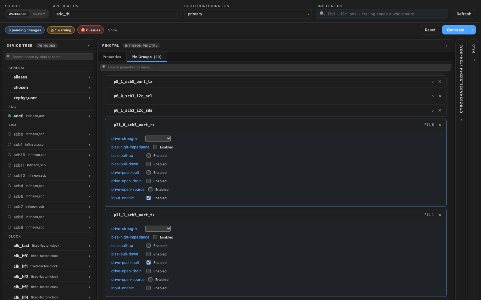
SCB modes
An SCB runs as a UART, an I2C or a SPI, depending on its compatible: infineon,uart, infineon,i2c or infineon,spi. The header flags pins of another mode, for example "scb3 runs as I2C (compatible "infineon,i2c"): TX is a UART or SPI pin of this SCB."
An SCB the board leaves as infineon,scb has no mode yet. Set its compatible in your overlay (outside the generated block) and rebuild before you route its pins.
XMC4500 and XMC4700
XMC4 pin nodes come from Zephyr's pin table for the chip: uart_rx_p1_4_u0c0 is USIC0 channel 0 UART RX on P1.4.
The input pin of a USIC or CAN is selected on the peripheral itself: input-src (UART, CAN), miso-src (SPI), sda-src and scl-src (I2C). When you route an input pin, the manager writes the selector with it, so the two always match. Moving the XMC4700 Relax Kit console RX from P1.4 to P5.0 writes:
&usic0ch0 {
    pinctrl-0 = <&uart_tx_p1_5_u0c0 &uart_rx_p5_0_u0c0>;
    input-src = "DX0D";
};

&uart_rx_p5_0_u0c0 {
    drive-strength = "strong-soft-edge";
    hwctrl = "disabled";
};
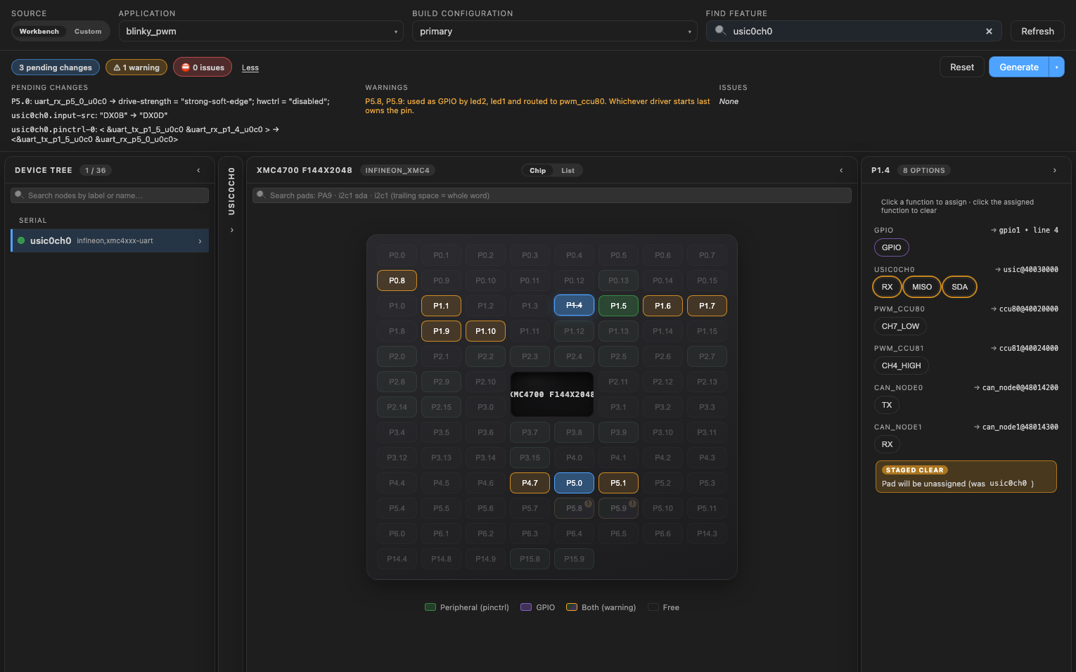
Output pins get drive-push-pull (drive-open-drain on I2C), with the drive strength and hwctrl = "disabled" the XMC4 boards use. The header flags a peripheral whose selector names another pin.
Functions listed only in XMCLib's pin maps are not offered, for example USIC chip select outputs (Zephyr's XMC4 SPI uses GPIO chip selects).