NXP LPC pinctrl in the Devicetree Manager
On NXP LPC (LPC51U68, LPC54114, LPC55S0x to LPC55S6x), a peripheral points to a pinmux node of its own, pinmux_<peripheral>, and the node's group lists the pins. Each pin is a name from NXP's pin header for your chip: FC2_RXD_SDA_MOSI_DATA_PIO1_24 is a FlexComm 2 pin on PIO1_24.
pinmux_flexcomm2_usart: pinmux_flexcomm2_usart {
    group0 {
        pinmux = <FC2_RXD_SDA_MOSI_DATA_PIO1_24>, <FC2_TXD_SCL_MISO_WS_PIO0_27>;
        slew-rate = "standard";
    };
};
The screenshot uses the LPCXpresso55S69 board.
FlexComm pins
A FlexComm runs as a USART, an I2C, a SPI or an I2S, depending on its compatible: nxp,lpc-usart, nxp,lpc-i2c, nxp,lpc-spi or nxp,lpc-i2s. Each FlexComm pin has one role per mode, and the Functions card lists them all: TXD/SCL/MISO/WS is TXD as a USART, SCL as an I2C, MISO as a SPI and WS as an I2S.
- The header checks the pins of the mode the FlexComm runs: TXD and RXD for a USART, SCL and SDA for an I2C, the clock for a SPI.
- A FlexComm the board leaves as
nxp,lpc-flexcommhas no mode yet, and the header flags its pins. Set itscompatiblein your overlay (outside the generated block) and rebuild before you route its pins.
Here, CTS and RTS are added to FlexComm 2, the board's Arduino UART:
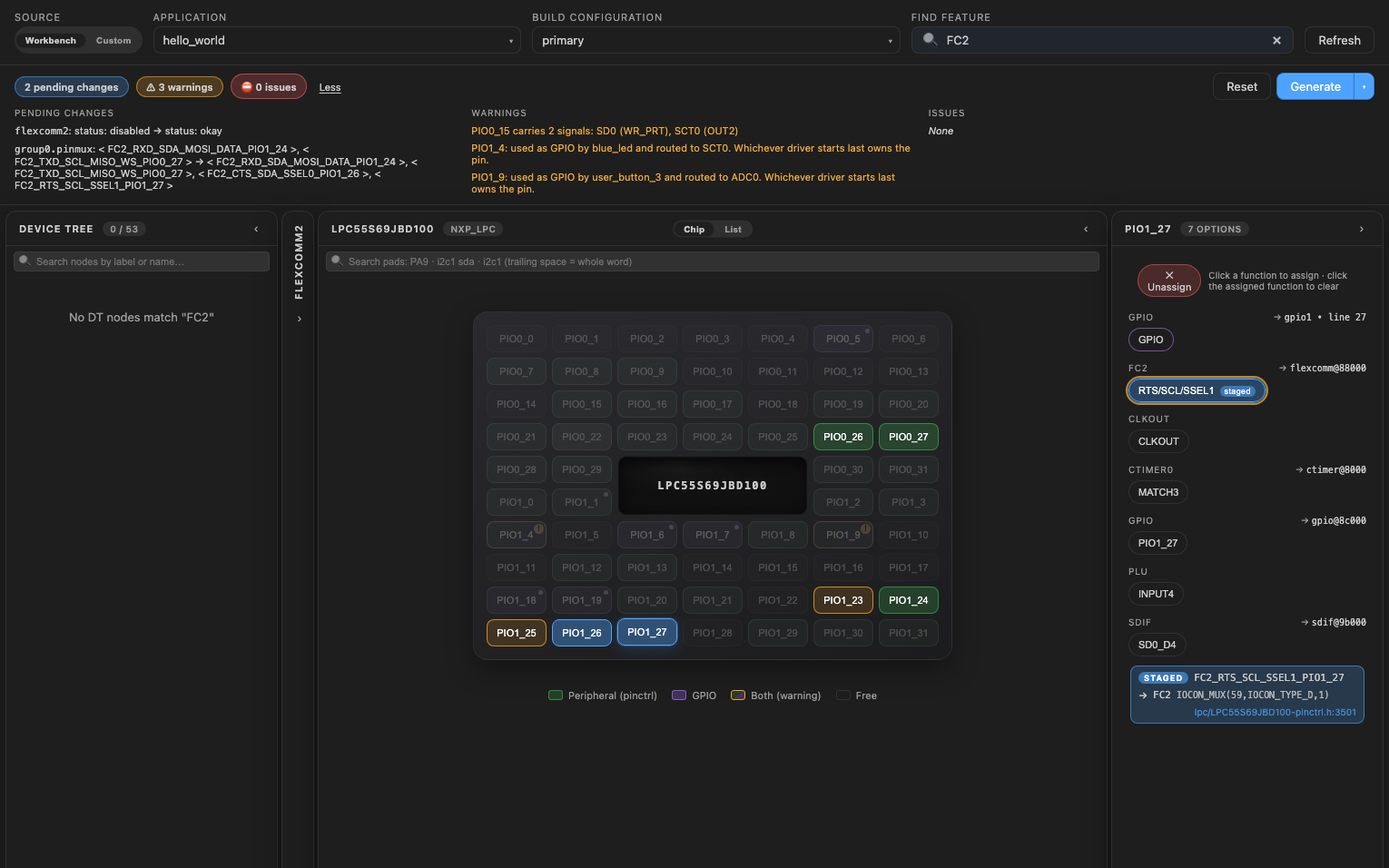
What Generate writes
When the peripheral already has a pinmux node, the new pins go in its group:
&pinmux_flexcomm2_usart {
    group0 {
        pinmux = <FC2_RXD_SDA_MOSI_DATA_PIO1_24>, <FC2_TXD_SCL_MISO_WS_PIO0_27>,
                 <FC2_CTS_SDA_SSEL0_PIO1_26>, <FC2_RTS_SCL_SSEL1_PIO1_27>;
    };
};
When it has none, the manager creates pinmux_<peripheral> and points the peripheral at it. The settings follow NXP's boards:
| Pins | Settings |
|---|---|
| All | slew-rate = "standard" |
| ADC, DAC, op-amp, comparator | nxp,analog-mode too (without it, the pin stays digital) |
| High-speed SPI | bias-pull-up too |
CTimer pins (PWM)
A CTimer that the board leaves as a timer becomes a PWM controller with its first MATCH pin. For CTIMER0 MATCH0 on PIO0_0:
&ctimer0 {
    pinctrl-0 = <&pinmux_ctimer0>;
    pinctrl-names = "default";
    compatible = "nxp,ctimer-pwm";
    #pwm-cells = <3>;
};

&pinctrl {
    pinmux_ctimer0: pinmux_ctimer0 {
        group0 {
            pinmux = <CTIMER0_MATCH0_PIO0_0>;
            slew-rate = "standard";
        };
    };
};
Unassigning that pin takes the change back. To drive an output from your application, see PWM.
NXP's pin header also lists the signals a pin can reach through the input mux (DMA triggers, pin interrupts, SCTimer inputs). Zephyr's pinctrl does not set the input mux, so the chip view shows a pin's own functions only.
Change pin settings
Open the pinctrl node, then its Groups tab. A group the manager creates shows its settings as checkboxes and lists; the board's own groups open like any node.